本篇内容最初于 2021 年 9 月 15 日发布于我的公众号 coding for psychers,因公众号停止更新,现将文章搬运到此博客
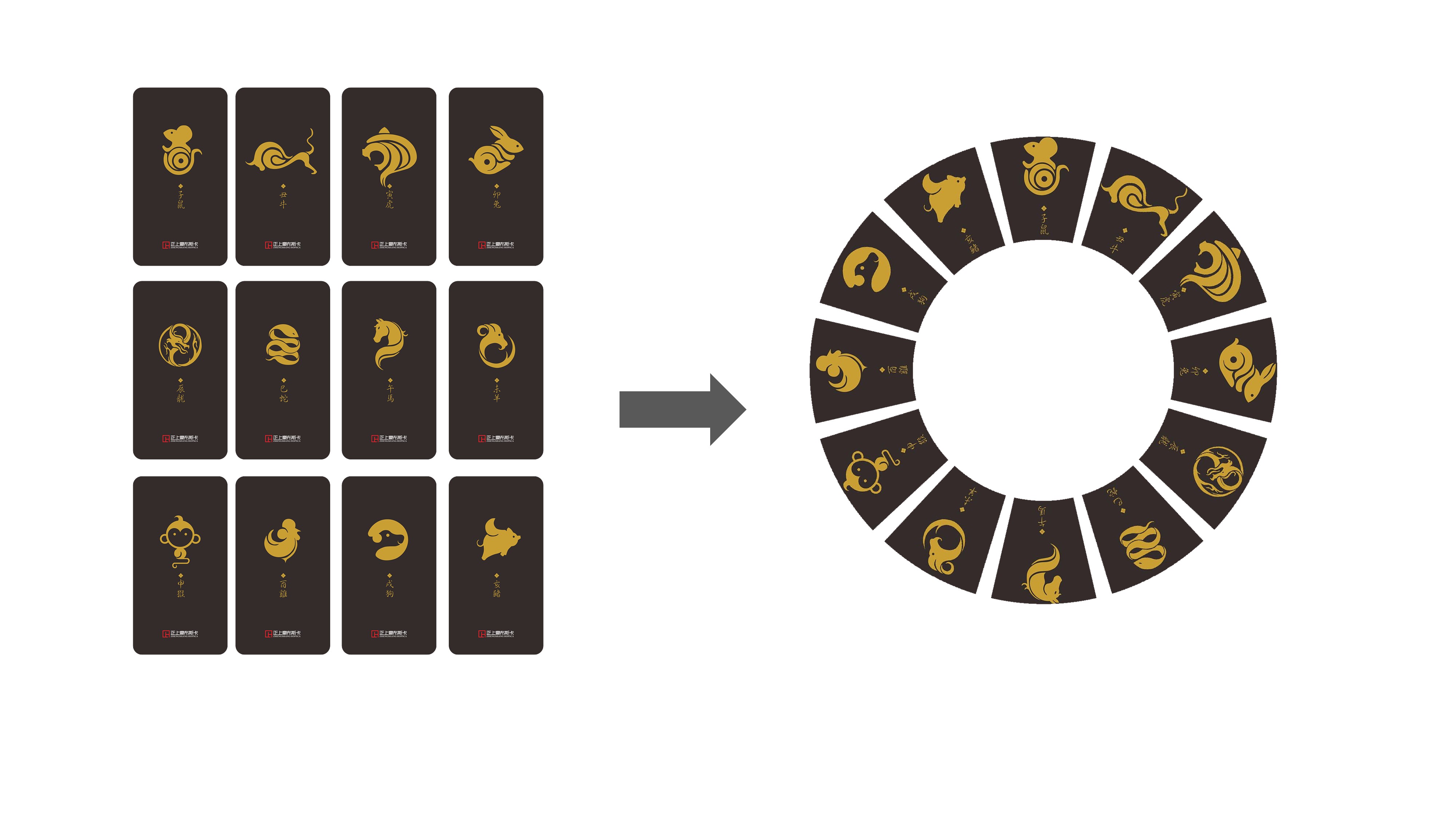
本篇教程将会讲解如何绘制如右图的效果:


图片素材:


1 思路分析
首先,我们来分析一下实现这个任务的思路。虽然解法多种多样,但是我所采用的思路是在每张图片中抠出一个扇形的区域,然后进行旋转并拼接在一起。
事实上,存在另一种思路,那就是,先将12张图片分别放到圆环上对应的位置,然后再盖一个蒙版。然而,这种思路存在一定的问题。当图片比较“胖”的时候,先放图片会导致图片彼此遮挡,从而影响最终的呈现效果。而先抠图,再拼接,就不会有遮挡的问题。
2 截取扇形区域
这里所说的抠图,是保留想要的区域,并将不想保留的区域替换为纯色。
我们从相对简单的抠图讲起——怎么抠出一个圆形?例如,我有一个矩阵:img = ones(600, 600, 3)。现在,我想要从矩形中心抠掉一个半径100的圆形,并将剩余部分替换为黑色,该怎么处理呢?
这就要说到逻辑数组了。MATLAB中,当我们将矩阵和数值比较时,得到的结果会是一个逻辑数组。例如:
 1
 2
 3
 4
 5
 6
 7
 8
 9
10
| a = [1 2 3; 4 5 6; 7 8 9];
b = (a > 5)
% Output:
% b =
%
% 3×3 logical 数组
%
% 0 0 0
% 0 0 1
% 1 1 1
|
逻辑数组可以用来作为矩阵的索引。此时,如果你运行a(b),你会发现,结果是[7; 8; 6; 9],正好是a中所有大于5的元素。因此,我们可以用逻辑数组提取数组中满足某个条件的元素。如果逻辑值为1,则提取相应位置的元素;否则不提取。我们可以用这种方法把a中所有大于5的元素设置为0:
使用逻辑矩阵提取元素时,需要注意逻辑矩阵和原始矩阵尺寸要完全相同。
而抠图的基本思路,就是用逻辑矩阵做一个“蒙版”,只要我们在逻辑矩阵中抠出一个圆形区域,那么我们就可以在原始图像矩阵中抠出一个圆形区域。然而,这是一件比较困难的事情,因为一个个像素点并不是连续的,我们很难表示出一个圆形。
我们再来看另一个知识点:前面的教程中,我们看到可以将矩阵作为图形呈现出来;而我们使用imwrite函数保存图片时,其实也是将一个矩阵保存为了图片。所以,我们可以先用fill函数画出一个圆,然后把这个圆截图,从而得到一个矩阵。这样,我们就有了一个可以表示一个近似圆形的矩阵。
 1
 2
 3
 4
 5
 6
 7
 8
 9
10
11
12
13
14
| img = ones(600, 600, 3); % The original matrix
hFigure = figure('position', [100 100 600 600], 'visible', 'off');
hAxes = axes('parent', hFigure, 'units', 'pixels', 'position', [0 0 600 600]);
theta = 0:(pi / 60):(2 * pi);
fill(300 + 100 * cos(theta), 300 + 100 * sin(theta), 'k', 'edgealpha', 0);
axis([0 600 0 600]);
axis off;
hFrame = getframe(gcf);
imgFrame = hFrame.cdata;
close(hFigure);
img(imgFrame > 200) = 0;
imshow(img);
|
画图部分没有什么可讲的,唯一需要说明的是我们给hFigure指定了一个visible属性。当将这个属性设置为off时,该窗口会被隐藏,但是我们仍然可以进行截图的操作。这样可以提供更好的用户体验,因为你的用户可能只想看到最后的抠图结果。重点需要说明的是第13行代码:img(imgFrame > 200) = 0。
我们先思考一下,因为原始矩阵img是白色的,所以我们应该通过逻辑矩阵选取圆形区域以外的地方,并将其值设置为0(黑色),而这部分在我们截取的窗口内容中为白色,也就是RGB为255的地方。因为截下来的图并不一定会完美保留色彩信息,所以我们可以给一个范围,只要RGB大于200的都算作白色。然而,问题来了,我们前面的教程中说到过,在MATLAB中RGB的范围是0 - 1,那为什么这里写的是imgFrame > 200而非imgFrame > 200 / 255呢?
在前面的教程中提到关于RGB的取值范围时,我们说到,可以暂时认为RGB的范围是0 - 1,因为这个范围和数据类型是有关的,而我们当时的示例中所使用的数据类型下,RGB的范围确实是0 - 1。这里,我们可以详细来说一说。MATLAB中,默认数值类型是double,使用double类型指定RGB值的时候,取值范围时0 - 1;然而,无论是我们使用getframe截图得到的矩阵,还是使用imread函数读取图片得到的矩阵,其数值类型都是uint8的,即8位无符号整数,其取值范围是0 - 255,而使用这个数据类型表示RGB的取值时,取值范围也是0 - 255。我们以后在表示颜色的时候,可以使用[1 0 0]这样的格式,也可以使用uint8([255 0 0])这种方式。不过需要特别注意,uint8,是unsigned integer的缩写,千万不要拼成unit8。
以上就是抠图的一个基本思路。不过,这里还是有一些地方需要完善的。在Windows下,系统有一个缩放比率,你可以在设置中进行查看。如果设置为125%的缩放率,那么对600 × 600的窗口截图后得到的图片大小是750 × 750,也就是600 * 1.25。所以,我们应该先获取一下系统的缩放率(是的,我们调了Java):
1
| scale = java.awt.Toolkit.getDefaultToolkit().getScreenResolution() / get(0, 'ScreenPixelsPerInch');
|
然后,我们需要将绘图阶段的一些参数根据这个缩放率进行调整,这样才能保证截图大小和原始矩阵尺寸匹配。
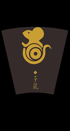
有了以上知识点,我们就可以对图像截取一个扇形区域。以其中一张图片为例:
 1
 2
 3
 4
 5
 6
 7
 8
 9
10
11
12
13
14
15
16
17
18
19
20
21
22
23
24
25
26
| image = imread('material/1.jpg');
width = size(image, 2);
height = size(image, 1);
scale = java.awt.Toolkit.getDefaultToolkit().getScreenResolution() / get(0, 'ScreenPixelsPerInch');
hFigure = figure('position', [100 100 (width / scale) (height / scale)], 'visible', 'off');
hAxes = axes('parent', hFigure, 'units', 'pixels', 'position', [0 0 (width / scale) (height / scale)]);
centerX = width / scale / 2;
centerY = -150;
innerRadius = 280;
outerRadius = 500;
theta = 77:0.5:103;
fill([(centerX + innerRadius * cosd(theta)) (centerX + outerRadius * cosd(theta(end:-1:1)))], [(centerY + innerRadius * sind(theta)) (centerY + outerRadius * sind(theta(end:-1:1)))], 'k', 'edgealpha', 0);
axis([0 (width / scale) 0 (height / scale)]);
axis off;
hFrame = getframe(gcf);
mask = hFrame.cdata;
close(gcf);
ringCenterToRectCenter = height / 2 - centerY * scale;
image(mask > 200) = 0;
imshow(image);
|
得到如下效果:
3 旋转图片
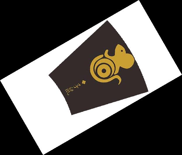
在MATLAB中,我们可以通过imrotate函数旋转图片。imrotate(a, angle)会将图片a逆时针旋转angle度。例如,我们将上面的图片顺时针旋转60°:
1
| imshow(imrotate(image, -60));
|
会得到如下图的效果:
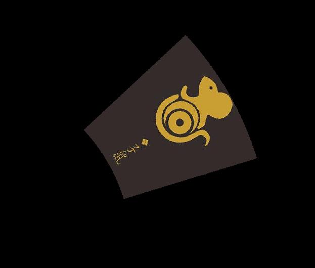
旋转后的原始图像部分大小不会改变,但是会被填补成一个正直摆放的矩形区域。为了方便演示,我们把原图片中扇形区域以外的地方用白色重新填充,来看一下效果:
4 拼接图片
因为旋转后的图片,除了目标区域以外都是黑色的,而黑色的RGB值是(0, 0, 0),所以可以把这些图片拼接到一个大的黑色矩阵上,这样,拼接后的图片整体背景仍然是黑色的。
 1
 2
 3
 4
 5
 6
 7
 8
 9
10
11
12
13
14
15
16
17
18
19
20
21
22
23
24
25
26
27
28
29
30
31
32
33
34
35
36
37
38
39
40
41
42
43
44
45
| clc, clear, close all;
image = imread('material/1.jpg');
% Get info of the images
width = size(image, 2);
height = size(image, 1);
% Get the scaling factor for windows
scale = java.awt.Toolkit.getDefaultToolkit().getScreenResolution() / get(0, 'ScreenPixelsPerInch');
% Initialize a window
hFigure = figure('position', [100 100 (width / scale) (height / scale)], 'visible', 'off');
hAxes = axes('parent', hFigure, 'units', 'pixels', 'position', [0 0 (width / scale) (height / scale)]);
% Draw mask
centerX = width / scale / 2;
centerY = -150;
innerRadius = 280;
outerRadius = 500;
theta = 77:0.5:103;
fill([(centerX + innerRadius * cosd(theta)) (centerX + outerRadius * cosd(theta(end:-1:1)))], [(centerY + innerRadius * sind(theta)) (centerY + outerRadius * sind(theta(end:-1:1)))], 'k', 'edgealpha', 0);
axis([0 (width / scale) 0 (height / scale)]);
axis off;
hFrame = getframe(gcf);
mask = hFrame.cdata;
close(gcf);
ringCenterToRectCenter = height / 2 - centerY * scale;
outImage = uint8(zeros((height + width) * 2, (height + width) * 2, 3));
for ii = 1:12
rot = -30 * (ii - 1);
image(mask > 200) = 0;
image = imrotate(image, rot);
rotatedImageWidth = size(image, 2);
rotatedImageHeight = size(image, 1);
bkg = uint8(zeros((height + width) * 2, (height + width) * 2, 3));
shiftX = ringCenterToRectCenter * sind(-rot) + height + width;
shiftY = -ringCenterToRectCenter * cosd(-rot) + height + width;
bkg(floor(shiftY - rotatedImageHeight / 2):floor(shiftY + rotatedImageHeight / 2 - 1), floor(shiftX - rotatedImageWidth / 2):floor(shiftX + rotatedImageWidth / 2 - 1), :) = image;
outImage = outImage + bkg;
image = imread(sprintf('material/%d.jpg', min(ii + 1, 12)));
end
imshow(outImage);
|
上面的代码中,我们将输出图片的宽和高都设置为了(height + width) * 2。这很容易理解,因为旋转后的图片的宽度和高度都不可能超过height + width,故这样设置输出图片的宽高一定能够将所有部分都容纳进去。另一个比较重要的部分是我们对拼接图片时偏移位置的计算。这基于一个前提,那就是不管怎么旋转图片,原始图片的中心仍然在旋转后图片的中心。通过简单的三角函数计算,我们可以得到这个位移量。
现在的效果如下:

5 设置透明背景
现在,效果已经出来了,但是问题在于,它的背景是黑色的,很丑。所以,我们可以给它设置一个透明背景。添加透明度通道的方法和上面的很类似。
 1
 2
 3
 4
 5
 6
 7
 8
 9
10
11
12
13
14
15
16
17
18
19
20
21
22
23
24
25
26
27
28
29
30
31
32
33
34
35
36
37
38
39
40
41
42
43
44
45
46
47
48
49
50
51
52
| clc, clear, close all;
image = imread('material/1.jpg');
% Get info of the images
width = size(image, 2);
height = size(image, 1);
% Get the scaling factor for windows
scale = java.awt.Toolkit.getDefaultToolkit().getScreenResolution() / get(0, 'ScreenPixelsPerInch');
% Initialize a window
hFigure = figure('position', [100 100 (width / scale) (height / scale)], 'visible', 'off');
hAxes = axes('parent', hFigure, 'units', 'pixels', 'position', [0 0 (width / scale) (height / scale)]);
% Draw mask
centerX = width / scale / 2;
centerY = -150;
innerRadius = 280;
outerRadius = 500;
theta = 77:0.5:103;
fill([(centerX + innerRadius * cosd(theta)) (centerX + outerRadius * cosd(theta(end:-1:1)))], [(centerY + innerRadius * sind(theta)) (centerY + outerRadius * sind(theta(end:-1:1)))], 'k', 'edgealpha', 0);
axis([0 (width / scale) 0 (height / scale)]);
axis off;
hFrame = getframe(gcf);
mask = hFrame.cdata;
close(gcf);
ringCenterToRectCenter = height / 2 - centerY * scale;
outImage = uint8(zeros((height + width) * 2, (height + width) * 2, 3));
alpha = uint8(zeros((height + width) * 2, (height + width) * 2));
for ii = 1:12
rot = -30 * (ii - 1);
image(mask > 200) = 0;
imageAlpha = uint8(ones(size(image, 1), size(image, 2)) * 255);
imageAlpha(rgb2gray(mask) > 200) = 0;
image = imrotate(image, rot);
imageAlpha = imrotate(imageAlpha, rot);
rotatedImageWidth = size(image, 2);
rotatedImageHeight = size(image, 1);
bkg = uint8(zeros((height + width) * 2, (height + width) * 2, 3));
tempAlpha = uint8(zeros((height + width) * 2, (height + width) * 2));
shiftX = ringCenterToRectCenter * sind(-rot) + height + width;
shiftY = -ringCenterToRectCenter * cosd(-rot) + height + width;
bkg(floor(shiftY - rotatedImageHeight / 2):floor(shiftY + rotatedImageHeight / 2 - 1), floor(shiftX - rotatedImageWidth / 2):floor(shiftX + rotatedImageWidth / 2 - 1), :) = image;
tempAlpha(floor(shiftY - rotatedImageHeight / 2):floor(shiftY + rotatedImageHeight / 2 - 1), floor(shiftX - rotatedImageWidth / 2):floor(shiftX + rotatedImageWidth / 2 - 1)) = imageAlpha;
outImage = outImage + bkg;
alpha = alpha + tempAlpha;
image = imread(sprintf('material/%d.jpg', min(ii + 1, 12)));
end
imwrite(outImage, 'out.png', 'alpha', alpha);
|